True innovation
MAD-S is a truly innovative FPV-racing frame that benefits from high-end composites and production methods not commonly used in FPV-racing frames. The concept is based on one basic principle – lighter and stiffer frames fly better! The main reason for this is how drones flight controllers work.
Noise filtering
Drones uses flight controllers to maneuver by adjusting the propellers speed. To get feedback for the control loop a high speed gyro is used. The basic principle is easy to understand but in reality things get complicated. That’s because the gyro signal does not only contain information regarding true movements – it also contains noise. This is because motors and propellers generate a lot of vibrations that contaminate the gyro signal. To handle this, flight controllers use filters to separate gyro signals for true movements from signals representing vibrations. There are many approaches for how to filter the signal but the basic principle is simple. Low frequencies represents movements – high frequencies represents vibrations. Because of this the most basic filter is a low pass filter (LP).
The downside with filters is that they add latency – delaying signals from gyro to PID-controller. More filters and lower filter frequency increases latency. More latency makes the drone struggle when it comes to handling of fast movements. The most noticeable problem is what’s usually refers to as “propwash”.
Frame-stiffness
Here is where frame-stiffness makes a major difference! Vibrations caused by motors and propellers in a 5” racequad is originally well separated from true movements in terms of frequency. This should make filtering easy but with a flexible frame we are forced to lower the LP-filter frequency – adding delay. This happens if the drone self resonance frequency is lower than the original vibrations caused by motors and propellers. Note that this refers to the self resonance for the entire drone – which is depending on stiffness and weight/inertia of not only the frame but the entire quad – incl motors, propellers, ESC:s, etc. Because of this a more powerful drone with heavier motors needs to be even stiffer to avoid problems with vibrations.
So why don’t just use light and stiff frames? Because there aren’t any! All current designs have their weaknesses but this is what we have tried to overcome with MAD-S!
How it all started
The project started out as an attempt to improve one of the best current racing frames – the Carbix Zero. That design is both stiff, light and aerodynamic with vertical arms. Initially we just tried to tweak the current design but during the design process the idea of a radical new concept was born – MAD-S!
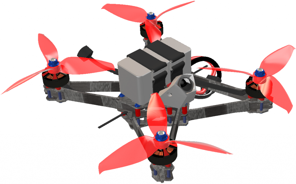
Design concept
Compared to Carbix Zero our design doesn’t have any long arms between the motors. Instead it has two short arms from each motor to the centerpod. This makes it very rigid in yaw. To make it stiff in pitch/roll the arms are extended more than twice their height between the centerpod plates. To avoid having the arms collide with each other between the plates there is a really tricky part with this design. There are 3 centerpod plates dividing the centerpod into two levels. 4 of the 8 arms are attached at the lower level and the other 4 at the top level. Because all arms are oriented in different directions it makes the centerpod extremely rigid – and the arms fixated rock solid. We call this concept an “A-frame”.
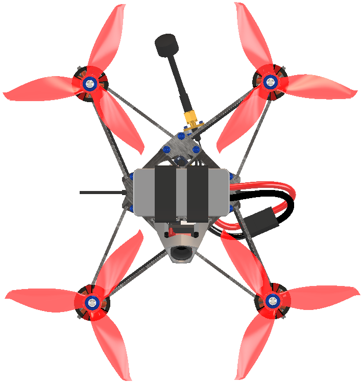
Identical arms
This also means that there are only two 2,3mm arms running under each propeller – reducing drag compared to the three 2,0mm arms in Carbix Zero. Another clever feature is that all arms are identical. To make it work, half of the arms are turned upside down. The frame also have similar stretch design as Carbix Zero. This is done only by moving the fixing points in the centerpod-plates. The top and bottom plate are also identical, one is just turned upside down compared to it’s identical counterpart. This reduced the number of carbon fiber parts needed to only 4 variants – reducing the number of spare parts needed for the user.
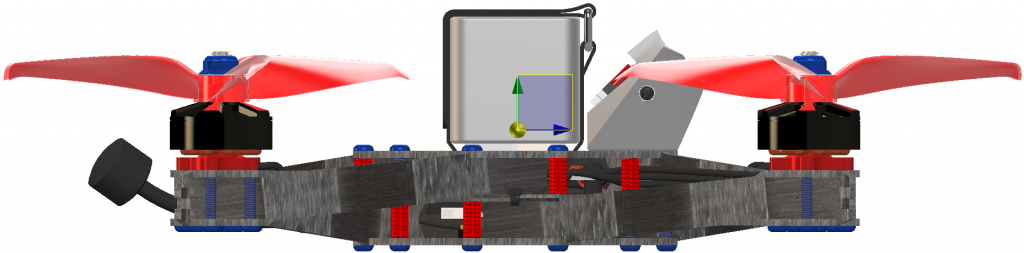
Top mount vs bottom mount
During the design and testing of this concept we have evaluated top mounted battery verses bottom mounted. From a strict flight experience point of view we found top mount to be far superior. This is because the center of gravity is very close to the trust plane with top mounted battery.. The frame is designed with dual battery straps – eliminating the problem with sliding batteries in crashes. We haven’t ejected a single battery in testing. Because top and bottom plates are identical – bottom mount is possible for user that prefer that.
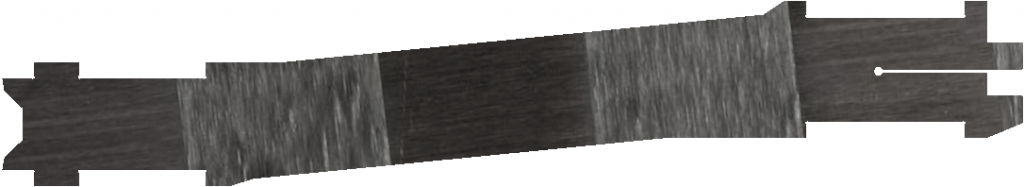
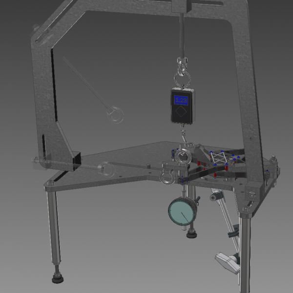
Custom laminates eliminates delamination
When we made the first prototypes of MAD-S we used regular 2mm quasi isotropic laminates – just as any other frame on the market. Right away the design proved to be just as stiff as we had hope for but it suffered from the same problem with delaminating arms as most other carbon fiber racing frames have. The broken parts where inspected by composite engineers with a clear verdict – It breaks due to no-optimal carbon fiber layup and fibers. Our solution: Make laminates with a asymmetric layup better suited for arms. Laminates with this layup are not common – they have to be tailor made. It took us a couple of attempts to get the balance between lengthwise stiffness and torsional stiffness just right but now we have a recipe for a laminates we have been using since the fall of 2018 without breaking or delaminating a single arm! Going to add the graph soon!
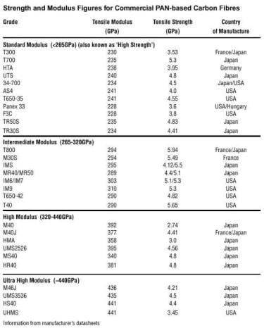
Intermediate modulus fiber
In the beginning we only used high strength (HT) carbon fiber like UTS50 from Tenax and T700S from Toray. This is common to what, in best case, other high performance drone racing frames uses. What most customers don’t know is that carbon fiber is not one type of fiber – it’s a big variety of different fibers with different properties where HT fiber is the relatively cheap, “standard” fiber. Trying to push the drone racing engineering forward we started looking at what future airliners will be built using – and that is not HT fiber, it’s intermediate modulus fiber (IM)! Compared to HT fibers, IM fibers are stronger, stiffer and has far superior impact resistance – exactly what we want in a racing drone! So why don’t anybody already use it? The answer is cost – it’s more than two times more expensive than HT fiber. Because of this we use IM fiber were it makes the biggest impact on performance and that is in the outer UD layers in the arms.
High modulus fiber
If stiffness is so important – why not go for high modulus (HM) fiber? That is because when going for stiffer fiber than IM you start losing strength and impact resistance. HM fibers are relatively brittle and not suitable for application that take a lot of beating. IM is the strongest fibers on the market and the sweet spot for many applications in the aerospace industry – including race drones.
When looking at the chart down below it looks like there are stiffer/stronger fibers then M30S – why not go for them? The answer comes from a big study of impact resistance. In this study a big number of tubes where manufactured using different combinations of fiber and resin systems. These tubes were then impacted in an impact machine and then bent until failure in a tensile machine. Bottom line was that tubes manufactured using M30S fiber far exceeded any other tested combination in performance after impact – even outperforming IM fibers that have higher strength/stiffness on paper. The results are still under investigation but it is believed that the reason for this lies in the interface between fiber and resin system used.
A composite consist not only by fibers but also of resin (epoxy) and for these two to stick to each other, fiber manufacturer apply sizing to the fibers that works as a primer. It is believed the resin system was not fully compatible with the sizing used in with the stronger IM fibers. M30S however are well known to have one of the best sizings on the market, making composites made out of it outperform most other combinations in real life applications.
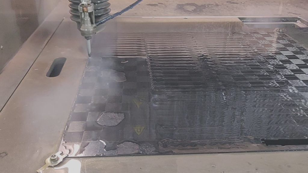
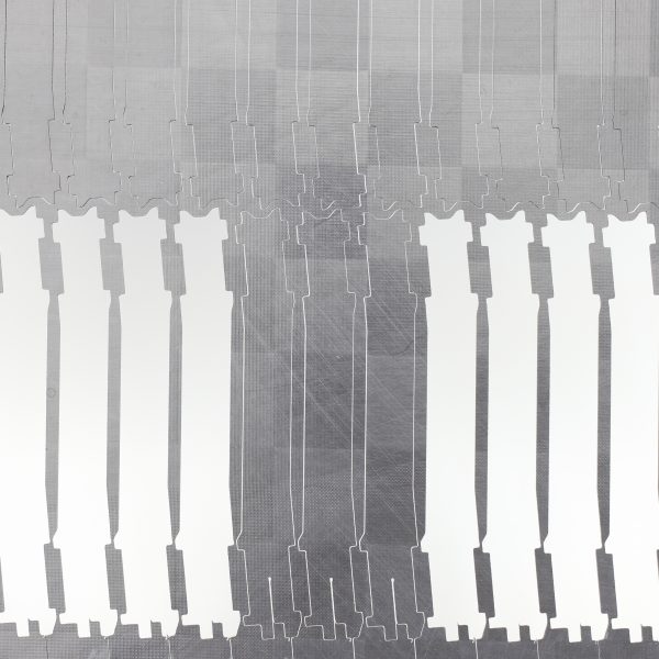
Micro water jet cutting
Most current 5” FPV racing frames are cut using milling. This method is time consuming and therefore a big part of the manufacturing cost. With more expensive materials we need to reduce cutting time to get an overall production cost that is on par with current concepts. The solution we found was micro waterjet cutting. This is a technique that only been commercially available for the last 10 years and differentiates itself from normal waterjet by cutting with a smaller beam – 0,3mm or less in carbon fiber laminates combined with higher precision – down to 0,01mm tolerance. This makes it possible to cut small inner radiuses – something that is very useful in the MAD-S concept because of the design with square tabs and slots.
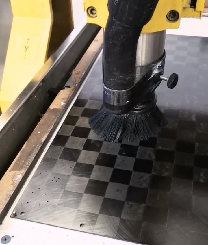
Start hole drilling
Waterjet cutting in carbon fiber laminates have one major drawback and that is the well known problem with delamination when doing “punch throughs”. When cutting arms that doesn’t have any holes this is not an issue because the punch throughs is done a few millimeter outside of the contour so that delamination does not affect the finished part. However, for all other parts in the MAD-S concept we need to make a lot of small holes without causing any delamination. We tried to overcome this by tweaking machine parameters when doing the punch throughs but came to the conclusion that this method is not reliable enough to be used in commercial scale production. There are a few micro waterjet machines equipped with a start hole drill that could overcome this issue but drilling takes a lot of time so this is not realistic for mass production. The solution we found was to combine waterjet cutting with drilling in a relatively cheap milling machine that is custom made for milling in carbon fiber plates. In this process the cutting pattern is generated at the waterjet machine shop and all startholes and two reference holes are exported to a DXF-file. This file is sent together with the laminates to the milling machine shop that stacks 2-3 laminates on top of eachother and drills all startholes and reference holes in one cycle. The laminates are then sent to the waterjet machine shop that fixture the laminates in the waterjet machine using the reference holes and then cut all contours starting every cut in a pre-drilled hole – eliminating all punch thoughts and thereby avoiding delamination.
TeXtreme™ Spread Tow Fabric
Last but not least comes the outer layers of the laminates. Nearly all laminates used in race-drones are made out of a core consisting of multiple layers of unidirectional (UD) carbon fiber covered with outer layers of fabric. So are also the laminates developed for MAD-S. The straight strains in the UD layers are the one that take up most of the load while the purpose of the fabric is to protect the sensitive UD layers from impacts that could make them crack. In most cases manufacturers claim a 3K carbon have been used – but what does that mean? Well, it means that the fabric in the outer layers have been woven using yarns consisting of 3000 filaments each. It does not give us any information of what fibers that were used in the UD layers but it gives a hint of the fabric fibers. The reason is that the best quality fibers are not manufactured in 3K yarns – eliminating them from being used in a 3K fabric. For example Toray only manufacturer T300 and T400H in 3K. T700S are made in 6K, 12K and 24K and the even better T700G are only made in 12K. So why not use a 12K fabric? With traditional weaving that would give us a extremely thick fabric with poor mechanical properties because of the waive fibers. So how can we use the high quality fibers and still get a thin fabric? The answer is Spread Tow Fabric (STF). In STF heavier, high quality yarns are spread into wide and thin tapes that are woven into plain weave with the characteristic square pattern. Because of this TeXtreme™ show performance similar to UD and have:
- 20-24% higher Modulus than 3k and 1k
- 60-75% higher Tensile Strength than 3k and 1k
- 20-30% higher Comp. Strength then 3k and 1k